Implementing a Circuit
Notes
- We discussed a three way voter problem
- Each voter has a button
- They press the button to vote yes.
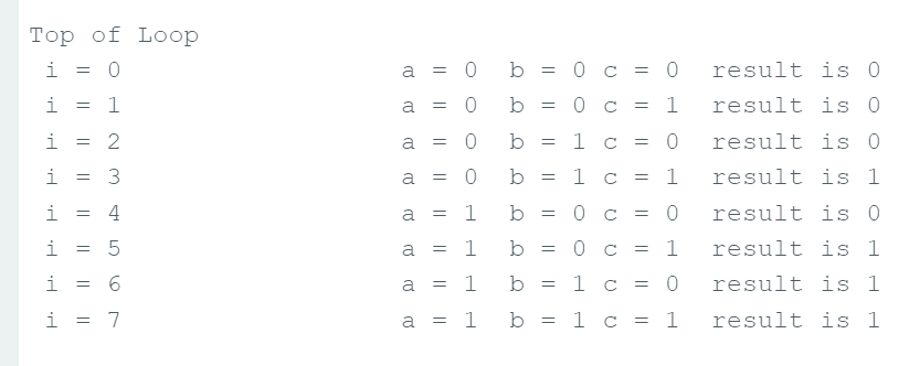
- Detect when at least two of three voters vote yes?
- We designed a truth table
a b c F(a,b,c) 0 0 0 0 0 0 1 0 0 1 0 0 0 1 1 1 1 0 0 0 1 0 1 1 1 1 0 1 1 1 1 1
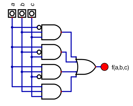
- Later we will learn to read a not simplified equation from this table
- f(a,b,c) = abc + abc + abc + abc
- This is not reduced.
- From this we produce a circuit in digital
-
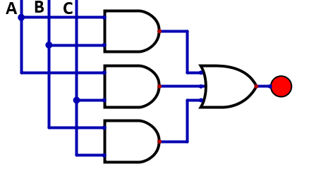
- We will later learn to optimize such a circuit.
- f(a,b,c) = ab + ac + bc
- But if you think about it a minute, it might make sense.
-
- To implement this, we will need two chips
- The 7408: Quad 2-input AND gates
- Datasheet
- The 7432: Quad 2-input OR gates.
- Datasheet
- Look at the pinout for each
- There is a notch at one end.
- The pins are labeled 1-14
- 1-7 on the left (with the pin at the top)
- 14-8 on the right (with the pin at the top)
- (They wrap around)
- Pins Usage
- 1,2 are inputs
- 3 is an output of f(1,2)
- 6 = f(4,5)
- 7 is ground
- 8 = f(9,10)
- 11 = f(12,13)
- 14 is +5v
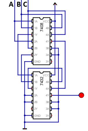
- On the 7408 we can wire
- a - 1
- b - 2
- a - 3
- c - 4
- b - 13
- c - 12
- ground - 7, 9, 10
- +5v to 14
- On the 7432 we can wire
- AND3 - 1
- AND6 - 2
- 3 - 12
- ground 4, 5, 7, 9, 10
- AND 11 - 13
- 11 to LED
- +5v to 14
-
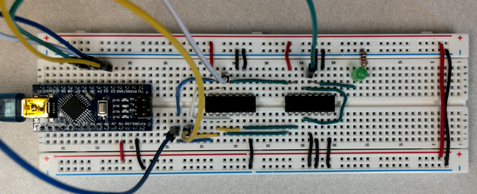
- My implementation
- The Arduino Nano provides a nice platform for development
- It has +5 and ground, which are wired to the outside rails and crossed over to the other side on the end.
- Pins labeled dX are for digital use
- You can either read or write to/from these pins
- I used
- a = d3
- b = d4
- c = d5
- result = d6
- I wired the two chips mostly as above
- I might have inverted b and c on the and.
- a = yellow
- b = blue
- c = white
- green is computed data.
- red is +5v
- black is ground.
-
- The code for this is c++
- You don't need include files for easy code.
- If you use libraries, you will.
- It is normal to declare pin constants
-
const int A_PIN{3};
const int B_PIN{4};
const int C_PIN{5};
const int RES_PIN{6};
-
- The function
setupis called once-
const int RES_PIN{6}; void setup() { // set up the serial communications data rate Serial.begin(9600); // set the pins for the right mode. pinMode(A_PIN, OUTPUT); pinMode(B_PIN, OUTPUT); pinMode(C_PIN, OUTPUT); pinMode(RES_PIN, INPUT); } - It initializes the serial line to the proper baud rate
- And sets the pin usage.
- A_PIN, B_PIN, C_PIN will be used for output, or writing values to the circuit
- RES_PIN will be used to read results.
-
- Declare a global int i, and initialize it to 0
-
}

// this could be static loop, but.
int i{0};

void loop() {
-
- You don't need include files for easy code.
-
loopis called over and over again.-
void loop() { // mark the top of the loop if (i == 0) { Serial.println("\n"); Serial.println("Top of Loop"); } -
Serial.println(a)is equivalent tocout << a << endl; -
Serial.print(a)is equivalent tocout << a - I don't think you can do multiple values on all boards.
-
- Exact the bits from i
-
} // extract the values from the state. int a = (i & 4) >>2; int b = (i & 2) > 1; int c = i & 1; - & is the bitwise and operator
- 5 = 101
- 101 & 001 = 1
- 101 & 010 = 0
- 101 & 100 = 4
-
a >> bshifts a to the left b times- 10011 >> 2 = 100
- This just makes sure that each is a 0 or a 1
- 4 >> 2 (100 >> 2) = 1
- 2 >> 1 (010 >> 1) = 1
-
- Some more output
- Then write the state to the circuit
-
  digitalWrite(A_PIN, a);
  digitalWrite(B_PIN, b);
  digitalWrite(C_PIN, c);
-
- Read the state
-
  delay(100);
  int pinState = digitalRead(RES_PIN);
-
- Some more output
- Increment i
i = (i + 1) % 8; - Wait a bit
dealy(2000); - And turn the circuit back to 0, or turn the led off.
-
- The Arduino Nano provides a nice platform for development
- the digital circuit file.
- The Arduino Code.