$\require{cancel}$
Registers
- Carpinelli discusses registers in chapter 7
- I want registers to continue to make use of the circuits we are discussing
- We will pick up more detail later.
- A register is a place to store data.
- They are constructed from flip-flops, which are constrcuted from transistors.
- They represent a different form of circuit.
- Combinational circuits are circuits where the ouptput is completely determined by the input.
- Sequentioial circuits have a state, and the output is determined by the input and the state.
- The staet of a register is the data it holds.
- Registers have some timing issues, but we will discuss that in the future.
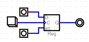
- Registers have
- A data in line of n bits. (D)
- A data out line of n bits (Q)
- A clock input
- They may also have one or more enable lines
- data in
- data out.
- Which might be enable
- They may have a reset line
- For the register in digital
- Place data on the data in line.
- Raise the enable line
- Pulse the clock line.
- When the clock goes from low to high, data on the data line will be stored in the register, if the chip is enabled.
-
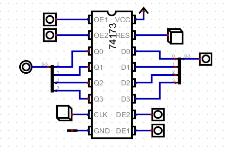
- There are several register chips, the 74173 is one.
- A 4 bit register.
- 4 data in lines
- 4 data out lines
- A clock
- A reset line
- Ground and power.
- Two output enable lines, need to be low.
- Two input enable lines, need to be low
-
- So we could build a simple PC
- I am using Digital's 4 bit adder.
-
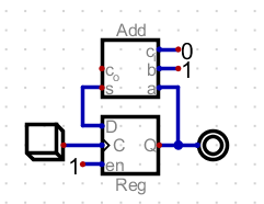
- But this is not the full operation of a pc.
- We might need to load the pc from the bus (jump and branch instructions)
- So I am going to add a mux
-
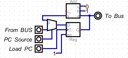
- Note that there are now two control lines
- PC source
- 0: pc ← pc + 1
- 1: pc ← bus3..0
- LoadPC
- Load the pc from the data source slected above.
- Note, Ben does not use this technique
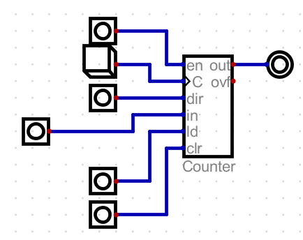
- He uses a counter.
- 4 data input bits.
- 4 data output bits.
- A clock.
- A load li
- A direction line (count up or down)
- A clear line
- An enable line, only for
- To count up
- enable on, dir off, pulse clock
- To cound down
- Enable on, dir on, pulse clock.
- To load
-
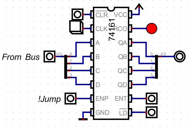
- This is our previous circuit bundedled into one.
- The 74161 is an example of this.
- It is a bit more complex.
- Clear, LD are all not lines, so they should be high
- To increment the clock
- ENP, ENT, LD and clr are high.
- Pulse the clock.
- To load from bus
- Set everything but clr to low.
- Put the data on the A-D
- Pulse the clock.
-
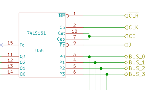
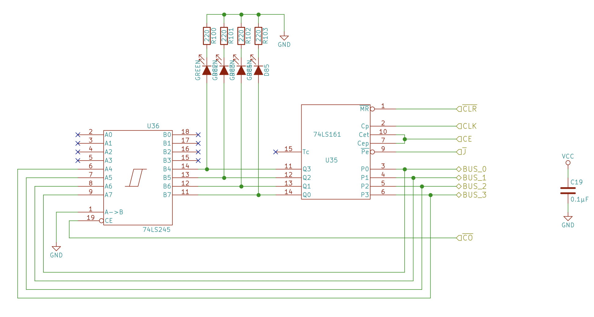
- This is the chip that Ben uses.
-
-
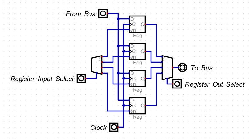
- We can build one more register related item, a register file.
- We discussed this last time, but I wanted a circuit.
- This one will allow four registers.
- It uses an encoder and a mux.
-
- The digit file