Control of the CPU
Objectives
We would like to :
- Understand the function of the control unit.
Notes
- Once again, we will use my 8 bit computer simulation.
- If you really want this, watch Ben Eater's Building an 8-bit computer from scratch.
- Or if you really really want it, buy his kit and build it.
- Or buy the parts on line and build it.
- Or buy a bunch of transistors and build the parts and build it. (insane)
- Load the this program: 0x15 0x26 0x47 0xE0 0XF0 10 20
- If we look at the 8 bit simulation at the μCode section, we start to see a deeper view of the computer.
- The A register is called ACC in these codes because ...
- There are two things we can do to a register, load it and read from it.
- Note there are two commands associated with the Acc register
- AI: ACC ← BUS: load the A register from the bus
- AO: BUS ← ACC: put the A register on the bus.
- From this we can infer that there are two control signals to the ACC register
- And the control unit issues those signals at the right time.
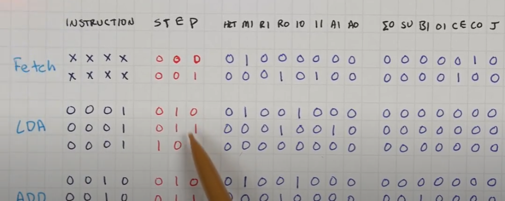
- This is strange, but Ben's computer supports a microcode for operation
- There is a micro instruction counter.
- And and a table indexed by instruction and instruction counter.
- This is just a 15 bit or so table that indicates what control lines should be lit.
-
 (From https://www.youtube.com/watch?v=JUVt_KYAp-I)
- We can watch this happen in the simulator.
- The μPC shows the value micro-pc
- The μIR; shows the control lines that are lit.
- From this, can we develop a more complex Fetch Decode Execute cycle algorithm for this computer?
- Major question: Do you want to go lower into how these components are built?